Arduino LoRa Network Part I: Radio Basics and Range Tests
Table of Content
My airconditioner's signals were the only ones I could not reproduce. Even when I could detect the same code every time after averaging the raw values from several recordings, the AC did not recognize them. Keep in mind that the code alternates between AC-ON and AC-OFF every time you press the button, so record at least two button presses.

Any person can use Voice Controlled Home Automation using Arduino project to control any electronic appliance in their home, shop, or industry. This can be done by an app on his/her Android Smartphone. We have interfaced the Arduino with the main circuit. The user can connect relays to various electronic home appliances. You can see in the block diagram below that Device 1 is Fan, Device 2 is Light and Device 3 is Buzzer.
Circuit Diagram of Voice Control Home Automation using Arduino and Bluetooth Module HC-05
That means, even if your AC remote uses a different frequency, it should still be detected. Moreover, set the value of the pins connected with the three bulbs to HIGH by using digitalWrite() function. Specify the pin as the first parameter and the value as the second parameter. This will ensure that all the bulbs are off initially. Next, we declare the Arduino pins that are connected with the LCD.
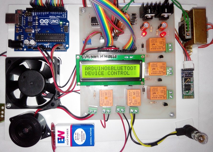
Here we will discuss Introduction to Voice Controlled Home Automation, Project Concept, Block Diagram, Components Required, Circuit Diagram, Working Principle, and Arduino code. Just say the needed temperature, control your home with voice or Android! Two units on synched Bluetooth link, RFID functions... This project will be helpful for physically challenged people who can use their voice to control anything.
How to Control the Air Conditioner A/C at Home With Arduino, Even Remotely!
Found on all platforms for all prices depending on what hardware and software version you are interested in. This system can be further modified so that users can vary the speed of the Fan. It can even be modified to control the buzzer volume. An LCD Display that shows the status of the devices like ‘Device 1 turned on’. However, other microcontrollers like 89s51, 89c51, 89s52, 89v51RD2, PIC18F4550, AVR ATmega32 can also be used.
Hi can i know should i declare the Ir LED pin ? Because when i run the coding, there's no action to my aircond. It should be stated that in the version of the code on Github reported, there is no level security password, to simplify a bit 'the project.
Step 4: READY TO GO
You will need to make some design choices and use the engineering design process to design your voice control system. Determine what features you need for your voice control system based on your plan. For example, if you want the system to work for everyone in your family, a speaker-independent module may be better. They may only work well when you are very close to them. That could be fine if you will use the device while sitting at a desk.
If we were to use the cited sensitivity of -146 dBm for each module, and a transmitting power of 30 dBm, plus an antenna of 5 dBi, we get a distance approximation of 30,000 km! However, if we go to the manufacturer’s datasheet, EBYTE claims an 8 km transmission range for the T30D module, and a 3 km range for the T20D module. Download grove_control_LED.ino and upload it to your Arduino. This is a slightly modified version of the example code that uses the commands "Turn on the light" and "Turn off the light" to control the Arduino's onboard LED. This loads the two commands you just recorded into memory for use with voice control.
Once connecting speak to the arduino with the commands you had set for the lights and fan to be turned on and off. Then the same is read by arduino as strings and then it performs the switching function of household items with the help of relay circuit. Add the following lines in the setup() function to activate the serial port.
Android is built on the open Linux Kernel. Furthermore, it utilizes a custom virtual machine that was designed to optimize memory and hardware resources in a mobile environment. Try saying the wake word followed by "Turn on the light." The Arduino's onboard LED (the one labeled "L" near pin 13) should turn on.
The current gain from the emitter to the collector terminal, Ic/Ie, is called Alpha, (α), and is a function of the transistor itself. The ratio of two currents (Ic/Ib) is called the DC Current Gain of the device and is given the symbol of hfe or nowadays Beta, (β). This project can be used to control the devices in our homes, offices, and industries.
From the above information, finally, we can conclude that user doesn’t have to get up from his position to manage the device. This is an advanced project which requires an Android-based device like smart-phone or tablet. Voice recognition technology is used inside the Android app. We can control device by using our voice.
For any other use, please contact Science Buddies. Do you have specific questions about your science project? Our team of volunteer scientists can help. Our Experts won't do the work for you, but they will make suggestions, offer guidance, and help you troubleshoot.
This function will be responsible for controlling the bulbs by comparing the received data with a predefined string. After completing the installation process, open the app and make sure the circuit is connected to the power supply and the Bluetooth module is on. Now click on the mic button to come on the app dashboard. The range of the LoRa modules will also be tested in New York City, where the path loss will be even more complex. We will likely see variations in range based on directionality and building heights - so the exploration of the true urban range of the LoRa wide area network will be tested and quantified.
What are the components that you have used here? I think tou havent mentioned all the components here and it will be great if you instruct me how to connect this device to our home circuit. Most relay boards are provided with 3 terminals for connection.


Comments
Post a Comment